Micrologix 1100 Wiring Diagram
Download Micrologix 1100 Wiring Diagram PNG. The micrologix 1100 controller ships with the battery wire connector connected. Internet explorer 9 or above are not supported because of javascript incompatibility.
Press f4 to open the driver window.
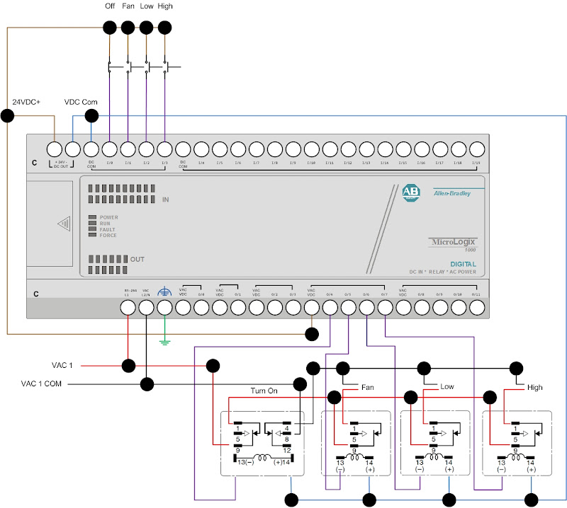
Your first diagram is correct for the wiring of a dc output to a relay. The micrologix 1100 plc channel 0 can connect directly to a serial port on a pc. Use the micrologix 1100 controller to remotely access controller data using a web browser. The cpu power and the output power are not internally connected so that the output power can be controlled by an emergency stop and separate fusing from the cpu the relay outputs on micrologix 1100 controllers are 5a relays.

Belum ada Komentar untuk "Micrologix 1100 Wiring Diagram"
Posting Komentar